Diving into the architecture of rv-runtime-generator
In the previous post[3], we explored the background, motivation and requirements for the rv-runtime-generator[4] tool. This post delves into the detailed design and architecture that powers this essential component of RISC-V runtime management.
Core Design Principle
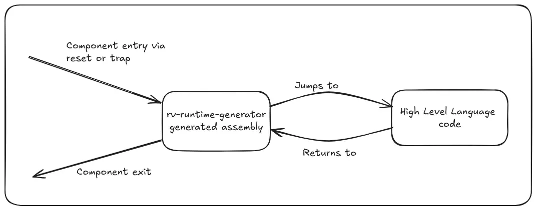
The rv-runtime-generator operates on a fundamental principle: all entry and exit points for components flow through generated runtime assembly code. This architectural decision creates a controlled, predictable environment where the processor consistently enters and exits components via the same generated runtime pathways.

Understanding Component Entry Points
Components can receive control in two primary scenarios, as discussed in our previous post:
Direct Control Transfer: This occurs during processor reset or when another component explicitly jumps to our component. The processor begins executing at a predetermined entry point.
Trap-Driven Entry: This happens when interrupts or exceptions redirect processor control to our component. The hardware automatically transfers control to our registered trap handlers.
In both cases, the processor lands in our generated assembly routines first, not directly in high-level language code. This assembly layer performs the critical environmental setup needed before safely transitioning to higher-level logic.
The Role of M-mode and S-mode Components
We are primarily targeting M and S-mode components here which typically act as service providers in the RISC-V privilege hierarchy. For example, an M-mode component often implements the Supervisor Binary Interface (SBI)[1], providing essential services to supervisor-mode software. Similarly, an S-mode kernel component manages and coordinates user-mode tasks.
These components handle several key responsibilities:
Boot time responsibility:
- Hardware Initialization: Setting up processors, memory controllers, and peripheral devices
- Data Structure Management: Establishing runtime data structures
Run time responsibilities:
- Service Provisioning: Responding to requests from lower-privilege software
- Interrupt Handling: Managing external interrupts and system events
- Data Structure Management: Maintaining runtime data structures
- State Management: Coordinating system-wide state transitions
An important aspect of these components is that they remain resident in memory even after completing their immediate work. They maintain their state, data structures, and readiness to service the next interrupt, exception, or service request. This resident behavior is crucial for system components that must provide ongoing services.
The Control Flow Architecture
The beauty of our architecture lies in its circular control flow pattern:
1. Entry Processing When the component receives control (via reset or trap), the generated assembly code immediately takes control.
2. Environment Setup The assembly routines configure the processor environment — setting up stack pointers, saving necessary registers, and establishing the execution context needed for high-level code to operate safely.
3. High-Level Logic Execution Control transfers to the high-level language code, which performs the actual work. This might involve processing an interrupt, handling a system call, or managing a hardware event. The high-level code focuses purely on business logic, knowing the environment is properly configured.
4. Controlled Exit Critically, the high-level code returns control to the generated assembly rather than jumping directly to its destination. This assembly layer then handles the exit process, restoring processor state and transferring control to the appropriate lower-privilege component.
Why the Circular Flow Matters
This circular control flow isn’t just elegant — it’s essential for several practical reasons:
Consistency and Predictability: Every component entry and exit follows the same pattern, making the system behavior predictable and easier to reason about. Developers can rely on consistent state management regardless of how control was transferred.
Simplified State Management: RISC-V systems can encounter complex scenarios like nested traps, where an interrupt occurs while processing another interrupt. Our architecture handles these situations cleanly because all state transitions occur in the controlled assembly environment.
Enhanced Debuggability: Complex control transfers are notoriously difficult to debug. By centralizing these operations in generated assembly code, we create well-defined debugging points. While assembly debugging has limitations compared to high-level language debugging, having consistent entry/exit points makes system behavior more traceable.
Clearer Mental Model: The circular flow creates an intuitive mental model for developers. They know that components are entered via assembly, do their work in high-level code, and exit via assembly. This clarity reduces cognitive load when reasoning about system behavior.
The Trapframe: Bridging Assembly and High-Level Code
Now that we’ve established the foundation of component entry and exit through runtime-generated assembly, let’s examine how high-level language code can inform the assembly code where to exit after completing its work. This is enabled through the use of a trapframe.
What is a Trapframe?
The trapframe is a multi-purpose data structure defined by the runtime that records the architectural state of the processor at the point where control transfers to the component. Think of it as a snapshot of the processor’s execution state, including:
- Unprivileged general purpose registers (x1 to x31)
- Program counter
- Privileged control and status registers (CSRs) like status register (mstatus/sstatus), trap cause register (mcause/scause), trap value register (mtval/stval)
- Floating point registers (general purpose and control/status registers, if supported by the target)
The Trapframe’s Multiple Roles
This data structure serves several critical purposes in our design:
State Preservation: It holds the execution state of the processor when control transfers to our component. This enables the component to preserve the interrupted state and restore it when returning to the interrupted software. Since the component needs registers to perform its work, saving architectural registers to the trapframe allows the component to use any registers without corrupting the interrupted state.
Interface Layer: It acts as an interface between high-level language and assembly runtime. The tool generates APIs that high-level language code can use to work with the trapframe data structure. Code can query various register states to determine why control was transferred to the component by examining trap cause and value registers. For service requests from lower privilege modes, other registers can be used to extract additional information. The RISC-V privileged specification [2] defines how to decode trap cause and value registers, the SBI specification [1] defines binary encoding for the Supervisor Binary Interface, and the RISC-V ABI specification [2] details the calling convention.
Control Mechanism: High-level language code can use generated APIs to update the interrupted state in the trapframe. This mechanism allows the high-level code to control where the component returns on exit from runtime assembly. Different scenarios require different actions:
- Service requests (made using ECALL): High-level code wants to start execution after the instruction that triggered the call
- External interrupts: High-level code wants to restart execution at the interrupted program counter
- Initialization/reset path: High-level code wants to set up the initial state of lower privilege software in the trapframe so control transfers to the lower privilege software entrypoint on exit
All these scenarios can be handled through a consistent interface exposed as APIs generated by the tool for working with the trapframe data structure.
Consistent Interface Design
To provide a consistent interface to high-level language code regardless of whether the component is entered via reset or trap, the reset path in the generated assembly runtime sets up a trapframe even though there’s no context to preserve. This enables high-level language code in the component to set up the initial state of lower privilege software using the same APIs to work with the trapframe as it would for trap handlers.
On component exit, the assembly runtime is responsible for popping content from the trapframe into the architectural registers, which results in control being transferred to wherever the high-level language code has determined. This is how high-level language code can control the behavior of the runtime assembly code.
Refined Architecture View
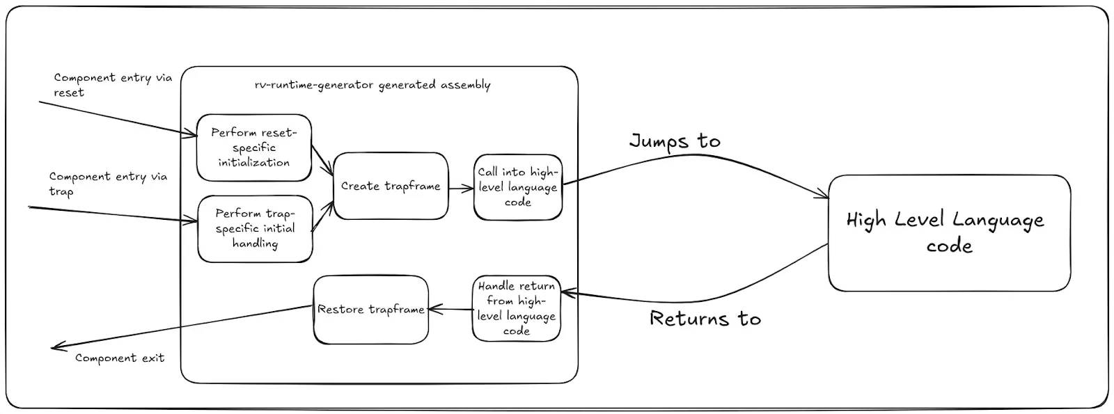
We can now refine our earlier architecture diagram to zoom in on the reset and trap entry and exit paths within the generated assembly runtime:

The diagram references initialization blocks specific to reset and trap handler paths, which we’ll explore in detail in subsequent posts.
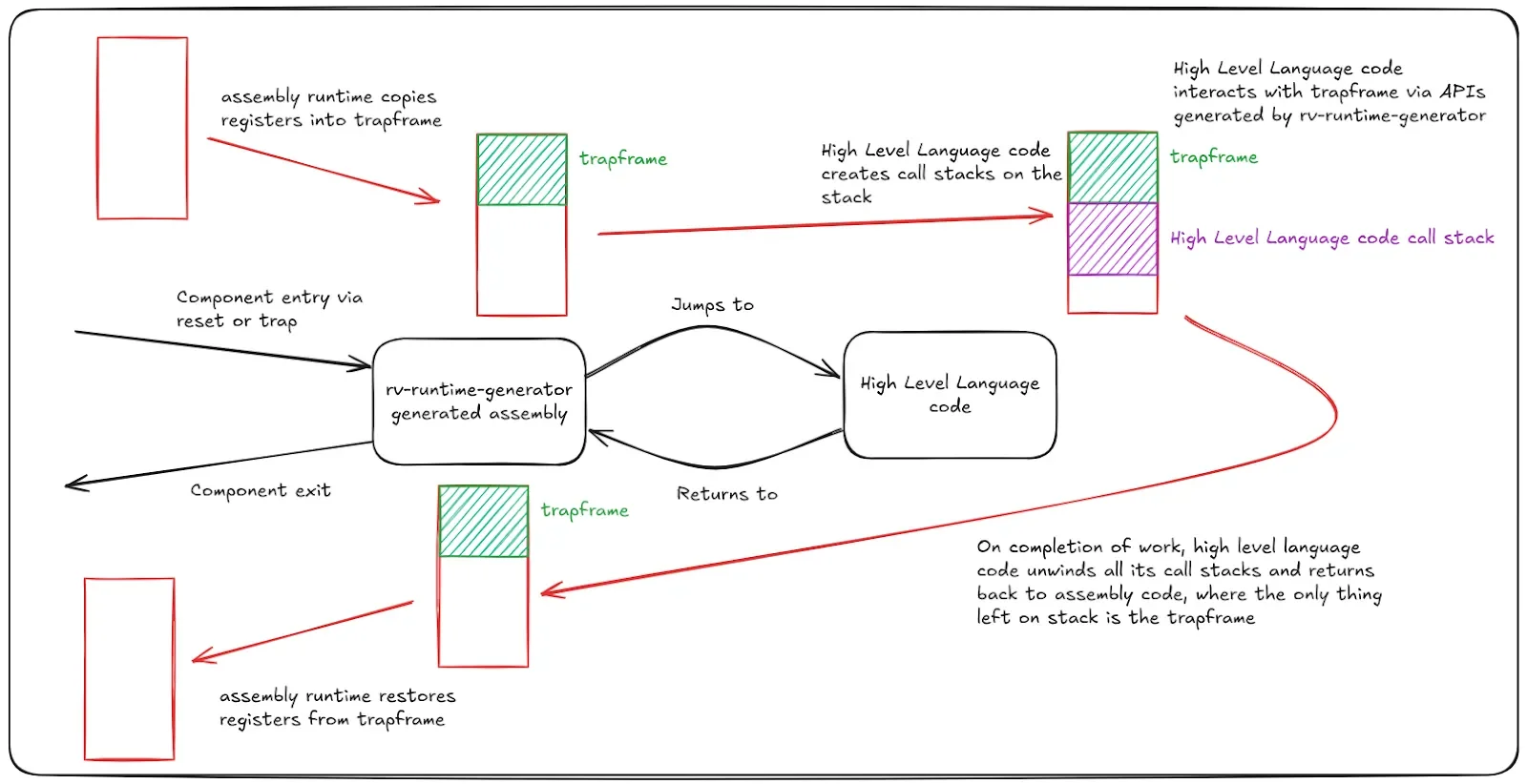
Stack-Based Trapframe Storage
You might wonder where this trapframe structure is stored. The runtime-generated assembly stores the trapframe structure on the stack of the current hart. Each RISC-V hart is a hardware thread — an independent thread of execution. Thus, each hart is allocated its own stack. We’ll cover the details of stack allocation and stack management for each hart in a later post.
Since the trapframe stores the context of the interrupted processor (hart), this structure is stored on the stack allocated for that hart. The state of the stack as we enter and exit the component follows a predictable pattern.

In case of nested traps, this flow becomes slightly more complicated since we can have more than one trapframe on the stack. We’ll examine these details in a subsequent post where we discuss trap handling and nested traps.
Trapframe Customization: Flexibility by Design
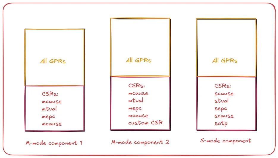
One of the primary goals of the rv-runtime-generator tool is to provide complete flexibility to the integrating component. Each component is unique with its own set of requirements, and this is reflected in the processor state it wants to save in the trapframe.
Real-World Examples
Mode-Specific Requirements: An S-mode component might want to save page management related registers (e.g., satp) whereas an M-mode component might not care about this.
Custom CSRs: Different RISC-V targets may have custom CSRs unique to their implementation. The RISC-V privileged specification [2] allocates a range of CSR addresses available for hardware implementers to customize for their RISC-V implementation. Depending upon the hardware implementation, a RISC-V component for this target might want to save any of these custom CSRs to the trapframe.
The combination of component requirements and RISC-V target variations creates virtually unlimited possibilities for trapframe customization.
Configurable Implementation
With this flexibility in mind, rv-runtime-generator provides complete control to the integrating component to specify at build time what it wants the trapframe to look like. The default implementation assumes that all GPRs and some CSRs (mstatus/sstatus, mepc/sepc, mcause/scause, mtval/stval) are part of the trapframe. If the component enables floating point support, then floating point GPRs and fcsr are also included in the trapframe structure.
However, the integrating component is free to choose its own set of registers that it wants defined as part of the trapframe structure, ensuring that the generated runtime meets the exact needs of each specific use case.

Looking Forward
In this post, we’ve examined the design principles for rv-runtime-generator and its use of the trapframe data structure. The circular control flow architecture, combined with the flexible trapframe interface, creates a robust foundation for building reliable RISC-V system components.
In the next post, we’ll dive into the details of boot initialization, exploring how the runtime sets up the initial execution environment and prepares the system for operation.
References
[1] https://github.com/riscv-non-isa/riscv-sbi-doc
[2] https://lf-riscv.atlassian.net/wiki/spaces/HOME/pages/16154769/RISC-V+Technical+Specifications
[3] https://medium.com/p/2c04dc41f53a
[4] https://github.com/rivosinc/rv-runtime/tree/main/rv-runtime-generator
