Boot up! Understanding RISC-V Runtime Initialization
In our previous post [1], we explored the architecture of rv-runtime-generator [3] and introduced its first key data structure — the trapframe. Now, we’ll shift our focus to the boot up path to understand the critical initialization steps performed by the generated runtime code. But first, we need to introduce a second, equally important data structure: the Thread Pointer Block, or tpblock.
Thread Pointer Block (tpblock): The Runtime’s Memory Anchor
As we learned previously, the trapframe structure is used to capture a snapshot of the hart state on entry into the runtime assembly. It is also used as a means by the high-level language code to drive the behavior of generated runtime assembly on the exit path. Thus, a trapframe is a “transient” structure which is created on every component entry and destroyed on component exit. If a component is entered recursively, multiple trapframes can exist on the stack for a single hart.
In contrast, the tpblock is a “permanent” data structure. It is created once at boot and persists throughout the lifetime of the component. The generated runtime assembly uses the tpblock for several crucial purposes which we will go through below.
Key Responsibilities of tpblock
1. Global Hart Information Tracking
Each hart has a unique integer ID, known as the hart ID, which is specified by the RISC-V Privileged Specification [2]. For M-mode components, the hart ID is read from the mhartid CSR. For S-mode components, the assumption made by rv-runtime-generator tool is that the hart ID is passed as an argument in the a0 general-purpose register (GPR) by the previous component. To provide a consistent interface, the generated runtime assembly stores the hart ID in the tpblock and exposes APIs for the high-level language code to access it.
RISC-V hart IDs are not guaranteed to be contiguous in a multi-hart system. The only requirement is that a hart with ID 0 must exist. To address this, the runtime assembly assigns a “logical” ID, called the boot ID, to each hart. The boot ID is a contiguous, 0-indexed number running from 0 to the total number of harts minus one. Like the hart ID, the boot ID is stored in the tpblock, and APIs are provided by the rv-runtime-generator tool to fetch it.
Both the hart ID (physical ID) and boot ID (logical ID) are determined during the initial boot sequence and are permanently stored in the tpblock. The rv-runtime-generator also generates APIs for converting between these two ID types.
2. GPR Stash Before Trapframe Creation
When control is transferred to a component’s entry point (either a reset or a trap handler), the runtime assembly has no free GPRs to work with. Arguments may be passed in GPRs during reset, and these must not be corrupted. Similarly, during a trap, the GPR state must be preserved for later restoration. The reset path is slightly more flexible, as it can use the GPR temporaries, but the trap path is not.
To perform any work, including saving state to the trapframe, the runtime assembly needs temporary storage. It uses the tpblock as a stash to save some GPRs, making them available until the trapframe is created. Once the trapframe is created, all GPRs are free for use.
3. Scratchpad for High-Level Language Entry Point
As we’ve seen, the reset initialization and trap handling entry points share the paths for creating and restoring trapframes.
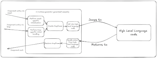
The create trapframe assembly routine needs to know where to jump to in the high-level language code after the trapframe is built. Since no free GPRs are available at this point, the tpblock serves as a scratchpad to temporarily store the address of the high-level language entry point. This information is later retrieved from the tpblock and used to jump to the correct location.
4. Tracker for current trapframe
The tpblock is also used to track the location of the current trapframe. Since multiple trapframes can exist on the stack due to recursive component entries in case of nested traps, the high-level language code needs a reliable way to find the most recent trapframe. The address of the current trapframe is stored in the tpblock, and APIs are provided to the high-level language code to access it. Thus, the tpblock structure can be thought of as the root pointer for all information required by the runtime assembly as well as the high level language code.
5. Tracker for stack pointer
Each hart is allocated its own stack. The address of the stack is saved in the stack pointer (sp/x2 GPR) and updated by high-level language code as it consumes the stack. When exiting a component to a lower privilege mode, the only reliable register available is the scratch register, which is guaranteed to hold its state. Since tpblock structure is our root for all information, the address of the tpblock structure is stored in the scratch register when exiting the component to lower privilege mode.
The allocated stack address is required to set up the stack again on the next component entry. Thus, the tpblock structure is the ideal place to save the stack pointer address. This allows the runtime assembly to retrieve the stack information whenever the component is re-entered from a lower privilege mode.
The following picture shows a logical view of the tpblock structure content. There are a couple of entries that we haven’t talked about yet — runtime flags and context pointer. We will get to these in later posts.
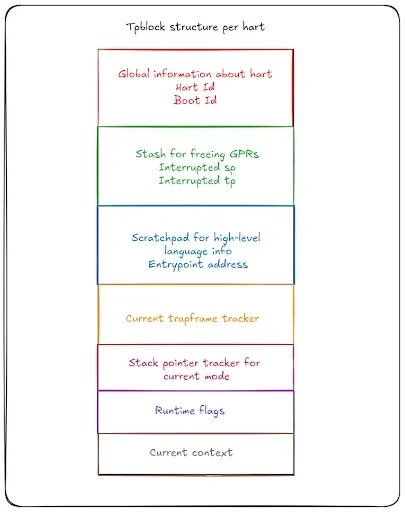
Tpblock storage
Unlike the stack-based trapframe, the tpblock is stored in the component’s data section. The rv-runtime-generator allocates an array of tpblock structures — one for each hart — using a stanza like this:
.section .data
tp_block:
    // Thread pointer block storage
    .rept X
    .dword 0
    .endr
During the initial boot sequence, the runtime assembly allocates a tpblock from this array for each hart. The index into the tp_block array corresponds to the hart’s logical ID (boot ID). The address of this structure is tracked in the tp/x4 GPR while the component is executing. When the component exits to lower privilege mode, the address of this structure is saved in the scratch register so that it can be retrieved back on the next component entry.
trapframe vs tpblock: A Comparison
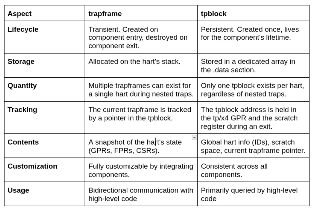
State of data structures across component entry/exit
The following diagram builds up on the one from previous post to show the state of tpblock, trapframe, scratch and tp registers as the control flows into and out of the component:
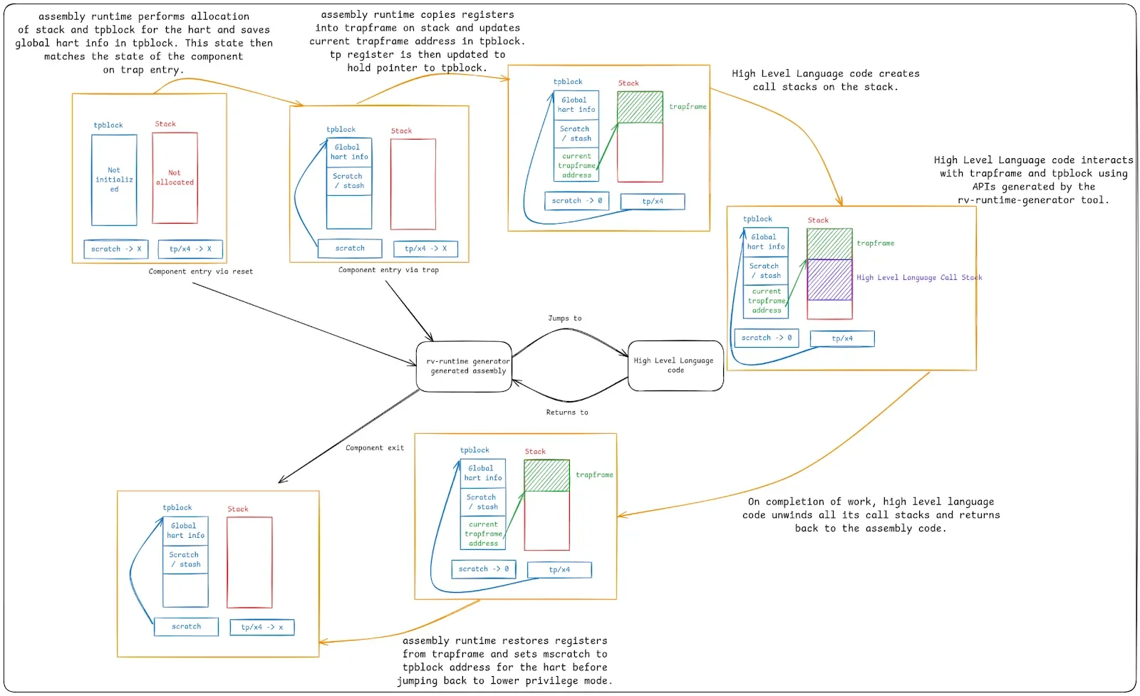
Reset Initialization: Step-by-Step Breakdown
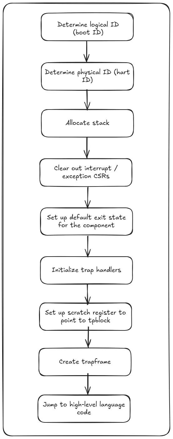
With our two primary data structures defined, let’s trace the steps the runtime performs during its first execution.
Determining logical ID (boot ID)
The runtime assembly’s first task is to assign a logical ID to the executing hart. In a single-hart system, this is always 0. In a multi-hart system, the rv-runtime-generator assumes atomic operations are supported by the target to ensure a unique, contiguous boot ID is assigned to each hart. This ID is crucial for allocating other hart-specific data structures like the stack and tpblock.
The rv-runtime-generator tool expects the integrating component to describe the target hart configuration (whether multiple harts are supported, whether atomic operations are supported) and catches any violation of assumptions at build time. We will go over the details of how rv-runtime-generator allows the integrating component to specify target configuration in a later post.
Capturing hart ID
Based on the privilege mode (M-mode or S-mode), the runtime reads the hart ID from either the mhartid CSR or the a0 GPR.
Allocating stack
The logical ID is used to allocate a dedicated stack for the hart from a special region defined in the linker script. We will go over the details of the linker script in a separate post.
Clearing interrupt/exception CSRs
The runtime initializes a clean state by clearing any pending bits in the interrupt enable and delegate registers. The high-level code is then responsible for enabling or delegating interrupts and exceptions as needed.
Setting up default state for component exit
The high-level language code is responsible for controlling where the runtime assembly jumps to on exit from the component. This is done by setting up the status and epc CSRs in the trapframe. To prevent undefined behavior, the runtime sets a default exit state. It configures the status and epc CSRs to return to the same mode and jump to a _park_hart routine that executes a wfi (wait for interrupt) loop, effectively halting the hart.
Initializing trap handlers
The runtime sets the trap base vector (mtvec/stvec) CSR to point to the entry point for all traps. The rv-runtime-generator currently supports only direct mode, where all traps jump to the same vector address.
Setting up scratch register
The scratch register is initialized to point to the hart’s allocated tpblock.
Zeroing out BSS
The runtime initializes the BSS region to all zeros. This is a crucial step that is performed only once by the primary boot hart, as the BSS region is common to all harts.
Creating trapframe
All required initialization is now complete. The runtime assembly stashes the hart’s state (GPRs, FPRs, and CSRs) into a new trapframe on the stack. The address of this trapframe is then saved in the tpblock.
Jumping to High-Level Language Entry Point
The runtime is now ready to transfer control to high level language code. It jumps to the specific entry point for the primary or secondary hart as specified by the integrating component. We will look at how the rv-runtime-generator can be customized by integrating components in a separate post.
Customization of the reset entry
As noted previously, one of the primary goals of rv-runtime-generator is to provide maximum flexibility to the integrating component to accommodate varying requirements. With this in mind, the rv-runtime-generator provides an option for the integrating component to jump to a custom reset entry point before the generated runtime assembly runs any code of its own. This custom entry point can be useful in scenarios like S-mode component wanting to set up SATP early or M-mode component wanting to set up some custom access permissions or any other component or target specific requirement that needs to be dealt with early on in the assembly code.
The generated runtime code to support custom entrypoint looks like this:
.section .text.entry, "ax"
.global _start
_start:
    // The component that uses this lib needs to provide 'my_custom_reset' in its own .S file
    la t4, my_custom_reset
    jalr ra, t4, 0
    // Determine boot id
Here, my_custom_reset is the custom entry point name that is specified by integrating components as part of their configuration.
Conclusion
In this post, we introduced the second crucial data structure of rv-runtime-generator which is the tpblock and looked at the details of reset initialization steps that are performed by the generated runtime. As we go ahead in this technical series, we will look into the trap handler paths as well as how the different integrating components can customize the rv-runtime-generator as per their requirements.
References
[2] https://lf-riscv.atlassian.net/wiki/spaces/HOME/pages/16154769/RISC-V+Technical+Specifications
[3] https://github.com/rivosinc/rv-runtime/tree/main/rv-runtime-generator
